NetApp Simulator Cluster Mode Getting Started Part 3
Preparing the **DataONTAP** 2nd Simulator Node
- Upload the 2nd node simulator files to an existing or create a new datastore.
- Register the simulator VM (right click .vmx file and register VM).
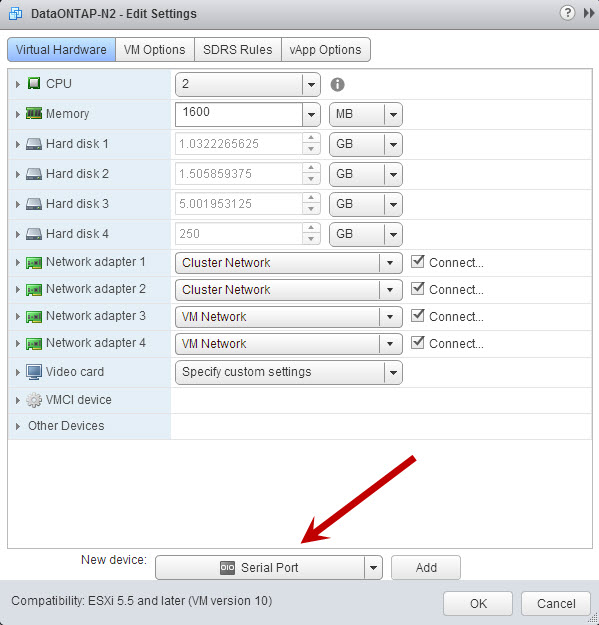
- Right click and select edit setting.
- Under the Virtual Hardware tab, add a new Serial Port device and click add.

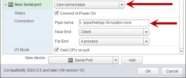
- Change the Serial Port output to “Use named pipe.”
- Enter the pipe name using the following syntax: \\. \pipe\”name of simulator folder on datastore”-cons and click OK.

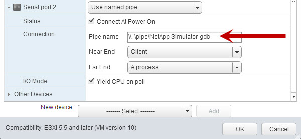
- Add a second Serial Port and change the output to “Use named pipe.”
- Use the same syntax as above for the pipe name, except change the -cons to -gdb and click OK.

Booting the DataONTAP Simulator 2nd Node
Note: The system ID is hardcoded on the DataONTOP simulator image. Each node requires a unique system ID to be permitted into the cluster.
- Open the simulator vSphere client console, press the space bar when the “Hit [Enter] to boot immediately, or any other key for command prompt.” is displayed.
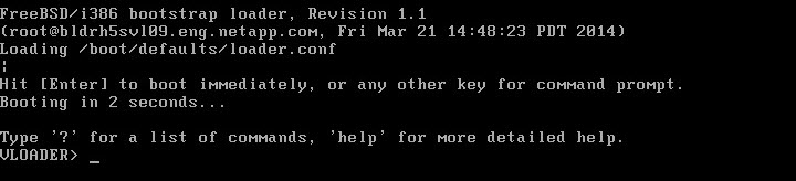
- At the VLOADER>prompt change the Serial Number and System ID for this node.

- Verify the information was saved correctly by using the following commands:
VLOADER> printenv SYS_SERIAL_NUM VLOADER> printenv bootarg.nvram.sysid

- Enter the boot command which begins the process that changes the serial number and system id.

- Follow the same steps in the previous post for Booting the DataONTAP Simulator 1st Node.


Joining the Cluster
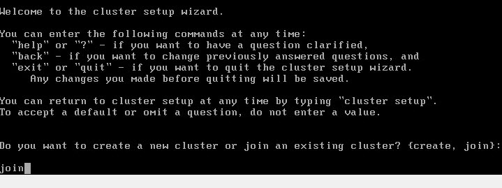
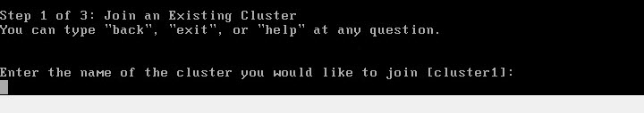
- At the “Welcome to the cluster setup wizard” screen you will be prompted to create or join a cluster. Since this is the second node in the cluster type join and press enter.

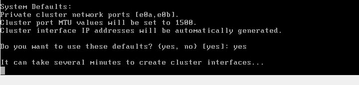
- When creating the cluster interfaces (e0a & e0b) you have the option of keeping the system defaults or changing the network defaults during the cluster configuration.
- Enter the name of the cluster you would like to join, in this example it is “cluster1” which was recognized by default.

- The 2nd node starts the joining cluster process.

- Enter the required network information for the cluster management and node interfaces.
- The cluster setup is complete.

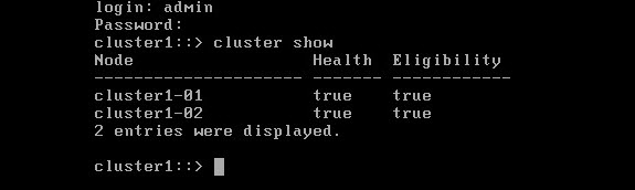
- To validate your two node cluster setup, log in and run “cluster show.”


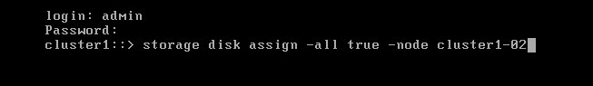
Assigning Storage
- To add storage to a node use the following command: Storage disk assign -all true -node “name.”
- To display disk information use the following command: Storage disk show.
